

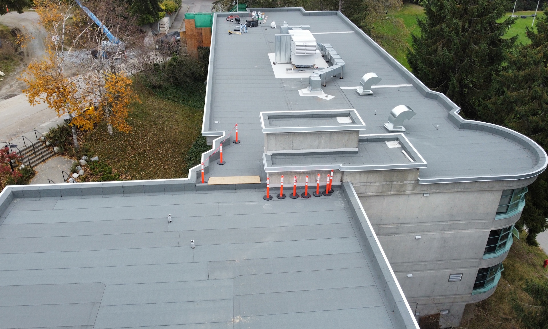
Thermal bridging is one of those building science phenomena that hides in plain sight. Present in nearly every commercial building enclosure, quietly undermining the performance of correctly specified and installed assemblies, and historically difficult to regulate because it is a condition of design and detailing rather than a product deficiency. Of all the places thermal bridging occurs in a commercial building envelope, the parapet may be the sneakiest: structurally familiar, architecturally ubiquitous, and until very recently, just beyond the direct discernment of the energy code.
For decades, the parapet lived in a sort of regulatory gray zone. Energy codes required R-values for roofs and walls. More recent requirements for air barriers and verified air tightness have helped. But the condition where the roof meets the wall – where two fully exterior-exposed planes of structural framing converge at the building perimeter – was addressed, if at all, mostly by inference or in footnotes and commentary. Project teams specified their assemblies, ran their energy models, and moved on. The parapet was somebody else's problem, or nobody's problem, depending on how you looked at it.
The 2024 International Energy Conservation Code (IECC) has now posited the parapet’s inherent challenges as everybody's problem. Long overdue, the IECC now requires that thermal bridges at the parapet and associated structural conditions be identified, addressed in the design, and inspected during construction.
The parapet: a thermal condition hiding in plain sight.
Being so familiar of a building element and perhaps because, conceptually, it extends beyond the dedicated thermal barrier of the building envelope, the parapet rarely receives the analytical scrutiny it deserves. As a protruding extension of the wall assembly along the roof perimeter, the parapet is – from a building science perspective – one of the most thermally complex conditions in a commercial building enclosure. Unlike the field of the wall, which has one face exposed to exterior conditions and one face protected on the interior, the parapet has both faces fully exposed to the exterior. In colder climates, this means heat loss is occurring simultaneously from two directions, and the structural framing within the parapet is often bridging the thermal control layer, often with no compensating insulation strategy in place.
The numbers are sobering:
A study by BC Housing examining a high-rise building found that nearly one-third of rooftop heat flow was lost through the parapet – losses that occur because buildings commonly terminate their wall insulation at the parapet, creating a thermal boundary interruption right at the roof-to-wall condition.
Research conducted by Payette through the AIA Upjohn Research Initiative used thermal simulations to quantify what most enclosure professionals have long suspected: studying typical commercial parapet construction, the researchers found that cold-formed metal framing and cast-in-place concrete parapet assemblies reduced theoretical R-values by 63% and 50% respectively – losses driven primarily by the insulation gap that opens up at the parapet condition.
A recent analysis by enclosure engineering firm Simpson Gumpertz & Heger (SGH), comparing thermal bridge performance across major U.S. energy codes and standards, found that the parapet registers as one of the highest heat-loss-per-linear-foot conditions in the entire building enclosure, with an unmitigated thermal transmittance ranging from 0.42 to 0.60 Btu per hour per linear foot of parapet length, depending on the code methodology applied. For context, that places the unmitigated parapet at a heat transfer rate roughly 30% to nearly double that of a typical window perimeter condition – a detail most architects already treat with considerable thermal scrutiny.
The parapet has persisted as a condition that many design teams either treat simplistically or with dismissed attention.
Why the parapet is so difficult to detail.
The structure required to support a parapet, whether supported by concrete masonry units, wood framing, or cold-formed metal framing, typically produces considerable complexities between the wall and roof assembly’s thermal control layers – and common construction techniques tend to maximize envelope surface area near this complex interface, amplifying the effect of the thermal bridge.
There are several compounding factors that make the parapet condition particularly resistant to simple solutions:
Competing geometric constraints. The roof insulation typically runs horizontally across the roof deck; the wall insulation runs vertically on the exterior or interior of the wall framing. At the parapet, these two planes of insulation must meet – and unless the detail is explicitly drawn to carry one continuously into the other, there will likely be a gap in the thermal control layer, resulting in a very energy-inefficient condition.
Structural penetrations. Guardrail posts, coping attachments, and blocking all require some form of attachment through or into the parapet, and each condition is a potential thermal bridge. Attaching a guardrail for fall protection or other rooftop accessories to the parapet wall creates additional opportunities for thermal bridging and/or air leakage. Metal fasteners and plates are particularly problematic – small in area but highly conductive, and common in mechanically fastened parapet assemblies.
Parapet height variability. A short parapet – say, 12 to 18 inches [305 mm to 457 mm] – presents a manageable detailing challenge. However, a taller parapet – perhaps 42 inches [1067 mm] or higher to serve as a guard and/or visually conceal larger rooftop equipment – on a high-rise building is a different matter entirely. The taller the parapet, the greater the exposed surface area and the longer the thermal bridge path through the structural framing. Solutions that work well at low parapets, such as wrapping continuous insulation over the top of the parapet wall, become less feasible as parapet height increases and coping blocking attachment requirements become more complex.
What the 2024 IECC now requires.
Historically, the parapet existed in a kind of regulatory gray zone – referenced obliquely in energy code provisions but never addressed with the specificity that its thermal significance warranted. The International Code Council (ICC) has changed this in meaningful ways with changes in the 2024 IECC. Specifically, new language requires that thermal bridges in above-grade walls be identified and explicitly addressed.
In the new section C402.7: Thermal bridges in above-grade walls, ICC introduces strict prescriptive design rules aimed at mitigating heat loss through elements that bypass the building's thermal envelope. The requirements cover specific structural and architectural intersections:
Balconies and floor decks (C402.7.1): Prohibits concrete decks and balconies from fully penetrating the thermal envelope without using approved thermal break devices or accounting for them in the wall's area-weighted U-factor.
Cladding supports (C402.7.2): Requires linear cladding supports to be offset, allowing continuous insulation to pass behind the element.
Structural beams and columns (C402.7.3): Mandates that penetrating steel or concrete structural members be wrapped with a minimum of R-5 insulation for at least 2 feet [610 mm] past the envelope's insulation layer.
Note that these provisions of the 2024 IECC regarding thermal bridging are no longer aspirational best practices; they are code-mandated design and documentation requirements.
The practical implication is direct: project teams can no longer simply specify an R-value for the roof assembly and wall assembly and consider the parapet resolved. The 2024 IECC requires that the thermal bridge at the parapet be identified on the construction documents, addressed through design, and inspected during construction.
Addressing thermal bridging and parapets in ASHRAE Standard 90-1 and LEED v5.
For teams pursuing high-performance building certifications that reference the ANSI/ASHRAE/IES Standard 90.1, such as the U.S. Green Building Council’s (USGBC) LEED v5 Building Design and Construction (BD+C), equivalent language and criteria addressing thermal bridging are emerging in the more recent editions.
Though not cited as a mandatory provision, new language in Standard 90.1-2022 explicitly addresses thermal bridging under the Prescriptive Building Envelope Compliance Path via 5.5.5 Linear Thermal Bridges and Point Thermal Bridges – including provisions for linear and point thermal bridge
Such harmonization between ICC, ASHRAE, and USGBC is not coincidental. The value of identifying, mitigating, and correcting thermal bridges is critical to the long-term success of a building and the industry is moving to address it.
Strategies for mitigating parapet thermal bridging.
There is no single correct solution that will ensure a parapet’s thermal continuity. The “right” approach depends on factors such as parapet height, structural system, cladding type, and climate zone. However, there are several basic strategies that design teams should be considering:
Continuous insulation to enclose the parapet. Where parapet height permits, wrapping continuous insulation across the top of the parapet and down both faces effectively encloses the structural framing within the thermal boundary. This approach works well for low parapets and concrete masonry unit (CM) or cast-in-place concrete parapet structures. The technique is best suited to short parapets and buildings insulated on the exterior; however, full wrapping may not be feasible where tall parapets, coping blocking attachment requirements, or designs with exposed structure or masonry coping are involved.
Thermal break at the roof-to-wall connection. Where structural framing extends from the wall into the parapet above the roof deck level, a thermal break at the connection point interrupts the conductive path. Thanks to its low thermal conductivity, a thermal break at the top of the wall where it connects to the roof effectively reduces heat losses, and for increased parapet heights (where the thermal bridging impacts can often compound) this solution can be implemented by transitioning the roof insulation and air barrier continuity directly into the wall insulation at the thermal break.
Transition the roof insulation into the wall insulation. Rather than terminating each insulation plane independently and hoping the gap is small, detailing the roof insulation to lap and connect to the wall's continuous insulation layer keeps the thermal control layer unbroken through the transition. This requires intentionality (i.e., explicit composite detailing) as to not separate roof and wall details; and it requires coordination between the roofing subcontractor and the wall subcontractor at the point where their scopes overlap.
Multiple layers of staggered insulation at the roof field. Detailing multiple layers of insulation at the roof with staggered joints, as outlined in IECC 2024 Section C402.2, can significantly reduce re-entrant air intrusion and convective heat loss at insulation joints. Design solutions to aid in reducing air intrusion also minimize the potential for moisture intrusion and condensation at the underside of the membrane. While this does not resolve the parapet condition directly, it improves the overall roof assembly performance in ways that compound with good parapet detailing.
Leverage LEED v5 and building enclosure commissioning. Once again, pursuing LEED v5 BD+C certification is akin to hitting the “easy button” to ensure that detailing is present that will exility address thermal bridges at transitions including parapets. LEED v5 BD+C adopts Standard 90.1-2019 (and starting in 2028, Standard 90.1-2022) by reference and building enclosure commissioning (BECx) requirements were added to the standard for the first time. Section 4.2.5, “Verification, Testing, and Commissioning,” was expanded and requirements were outlined for commissioning in accordance with ASHRAE/IES Standard 202, which calls for a “Design Review” to be performed by the Commissioning Provider (CxP) to evaluate project compliance with the Owner’s Project Requirements (OPR). At the project outset, when OPR is developed by the Owner, ensure that the “Design Review shall address thermal bridging between walls and roofs, including parapets and copings; and walls at foundations.”
Elect for enhanced commissioning. Electing for EAc5 Enhanced Commissioning under LEED v5 BD+C will require a building project comply with all tasks and deliverables referenced with ASTM E2947-21a: Standard Guide for Building Enclosure Commissioning, except Sections 7.2.4 and 7.4.3. This will include infrared imaging per ASTM C1153 or ASTM C1060.
The parapet as a design decision, not a detailing afterthought.
The through line of this article is simple: enclosure failures – thermal and otherwise – rarely originate in the field of well-specified and installed assemblies. They originate at the transitions between them. The parapet is the most consequential of those transitions precisely because it sits at the intersection of two fully exterior-exposed planes, involves structural conditions that compromise the thermal boundary, and has historically been treated as a termination condition by both the roofing trade and the wall trade with no single party responsible for the thermal performance of the combined assembly.
The 2024 IECC has now made that ambiguity a code compliance problem. For design teams pursuing LEED v5, it is also an energy performance prerequisite problem – however, pursuing LEED v5 certification can easily thwart the issue if enhanced commissioning is pursued. But for architects who adhere to the whole-enclosure mindset (see the previous article in this series), it is simply a design problem – and one that is entirely solvable when it is identified early, detailed explicitly, and coordinated across the enclosure team.
