The building envelope (or enclosure) is the primary barrier between a structure's interior and the external environment. It serves critical functions, including the management of heat flow, air infiltration/exfiltration, and moisture transfer by way of bulk water intrusion and/or vapor diffusion.
Every building envelope assembly should incorporate dedicated components that serve as at least one of the following three key management layers:
Thermal barrier
Air barrier
Water-resistive barrier (WRB or "weather resistive barrier")
A single component can serve multiple functions. In some instances, a fourth management layer—a vapor retarder—may be needed, depending on factors such as climate, interior conditions, the level of heat flow, and the vapor dynamics of the given assembly.
It is critically important to not conflate the distinct roles of these layers. For example, a WRB will prevent bulk water intrusion but allow both air and vapor to pass through. An air barrier, on the other hand, may or may not impede moisture, including vapor.
Defining Air Barriers
The International Code Council (ICC) defines an air barrier as "one or more materials joined together in a continuous manner to restrict or prevent the passage of air through the building thermal envelope and its assemblies."
Similarly, ASHRAE defines a continuous air barrier as "the combination of interconnected materials, assemblies, and sealed joined and components of the building envelope that minimize air leakage into or out of the building envelope."
By definition, an air barrier is designed to minimize air leakage through the building envelope—period. Thermal and moisture management are separate considerations.
The Importance of Air Tightness
A significant amount of energy is expended to heat, cool, and ventilate a building's interior. Air leakage is tantamount to leaving a building's windows open 24-hours a day, every day of the year. In a building with a poor performing (or no dedicated) air barrier solution, a quarter to half of the building's overall heat loss may come from air leakage.
Airtight envelopes also mitigate vapor transfer and potential condensation-related issues. According to a classic analysis by Building Science Corporation, as offered in their Builder's Guide for Cold Climates, during the heating season in a cold climate region, vapor diffusion through a solid a 4-foot by 8-foot sheet of gypsum board may result in about 1/3 quart (0.3 L) of water being transmitted to the interior. By comparison, the air leakage through a 1-square-inch hole in the middle of the gypsum board over the same period of time may result in approximately 30 quarts (28.4 L) of water being transmitted to the interior – approximately ninety times more water than through diffusion.
Types of Air Barriers
Mechanically fastened sheet membranes. Commonly referred to as "house wrap", these products are essentially sheet-like products that must be cut and fastened (often simply with staples) to the substrate and other building components.
Self-adhered sheet membranes. These are "peel-and-stick" membrane products and they are applied directly to a compatible substrate. Careful handing is necessary to avoid wrinkles and ensure proper adhesion.
Fluid-applied membranes. This type of air barrier is a liquid that is applied by either spraying or rolling onto a surface to form a "membrane." Once cured, these products form a seamless, monolithic barrier. Proper application is critical to ensure proper coverage, which is essential for durability and effective air sealing.
Spray foam insulation. This is a solution by which a thermal barrier can also function as an air barrier. As spray foam products expand and cure, they can also establish an air barrier; however, minimal thicknesses must be accomplished.
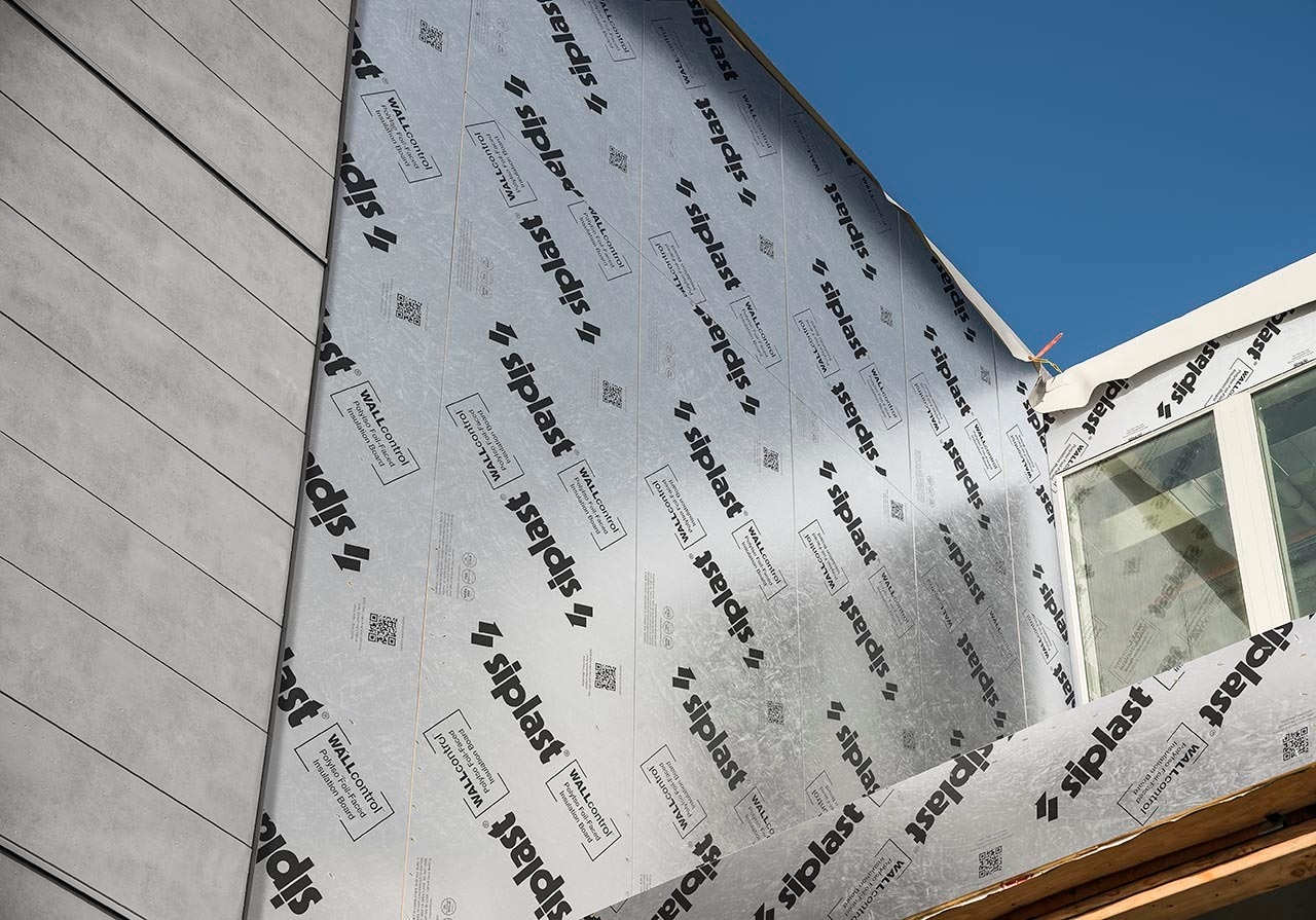
Bonded Membrane sheathing. These are "multifunction" sheathing panels, but it's important to note that proper airtightness can only be established through the combination of compatible tapes and sealants along seams, transitions, and penetrations.
Clarify the air barrier system type. As noted above, the air barrier can be accomplished through several systems. Make sure to design to specific system type.
Ensure continuity. Approach the air barrier system in such a way that, despite transitions resulting in using different system components, continuity is maintained. Minimize "breaks" by which a transition causes the air barrier to shift locations – and make sure that such shifts are adequately addressed.
Document critical details. Continuity is often compromised at joints, interconnection, and penetrations. Air barrier transitions should be detailed to ensure that conditions are conducive to maintaining continuity. At a minimum, the following conditions should be detailed:
Door and window frames.
Joints between walls and floors.
Building corners.
Foundation-to-above-grade wall transitions.
Wall-to-roof transitions.
Parapets and copings.
Building assemblies serving as ducts or plenums.
Wall and/or roof penetrations.
Indicate secondary system components. Caulking, gasketing, taping, and mechanical fastening can make or break the performance of an air barrier. These secondary system components should be indicated within project documentation.
Execution Will Make or Break the Air Barrier System
Specify performance testing and field inspection requirements. A plan for performance testing and field inspections should be captured in the project's technical specifications.
Coordinate the timing. Certain types of on-site testing must occur at specific points in the construction process. On-site testing should be coordinated within the construction schedule and ample time should be afforded to execute the testing requirements. Similarly, site visits and inspections must occur at specific points in the schedule to ensure that certain system components were properly installed.
Cross-trade coordination. This may initially seem like a given, but it is not. Trades are constantly coming and going from the jobsite and carrying out their respective portions of the work on a project. Yet, air barrier transitions often embody and impact components of the building envelope across numerous trades. Without proper coordination among subcontractors – such as framers, HVAC installers, electricians, and roofers – realms of intersection can become weak points in the continuity and/or quality of the air barrier system.
Code Requirements for Air Barriers and Air Leakage
Air barriers are commonly required by the latest model codes and standards:
2024 International Building Code (IBC) references the 2024 International Energy Conservation Code (IECC), which requires a continuous air barrier in chapter 4.
2021 International Residential Code (IRC) requires a continuous air barrier in chapter 11.
ANSI/ASHRAE/IES Standard 90.1-2022, which serves as the basis for the energy code in many jurisdictions, requires a continuous air barrier, as noted in chapter 5.
Note that in all of these cases, the type of air barrier system is never specified.
Performance Verification Matters
Measured Air leakage is emerging as a de facto method for building envelope performance verification in the latest model codes and standards. Third-party verified whole-building pressurization testing to determine the air leakage rate of the building envelope is now an established compliance pathway.
The table below notes the maximum air leakage rates for nonresidential buildings that typically applies in each of these documents. Please note that in each instance, there may be qualifiers, noted alternative compliance options, and exclusions.
Table: Maximum Air Leakage Rates for Nonresidential Buildings1
Model Code or Standard | Air Leakage Rate, cfm/ft2 (L/s m2)2 |
Modeled baseline air leakage rate (per ANSI/ASHRAE/IES Standard 90.1-2022) | 1.00 (5.1) |
Typical leaky building (general reference) | 0.60 (3.0) |
ANSI/ASHRAE/IES Standard 90.1-2022 | 0.35 (1.8) |
2024 International Energy Conservation Code | 0.35 (1.8) |
2024 International Green Construction Code | 0.20 (1.0) |
2024 Phius CORE Standard (performance path) | 0.08 (0.4) |
1 General requirements. The information in this table is for basic reference.
2 Air leakage rate noted per unit area of the building thermal envelope at a pressure differential of 0.3 inch water gauge (75 Pa).
Building Enclosure Commissioning (BECx)
Model codes and standards do not yet mandate building enclosure commissioning (BECx) across all projects, but they do incorporate specific commissioning-related requirements for certain building envelope components, particularly concerning air leakage and insulation. In accordance with best practices, the BECx plan should begin with formal review milestones no later than the design development process and the construction phase components of the BECx plan should be defined within the project's technical specifications. On-site performance testing and field inspections should be either executed by or coordinated with the commissioning authority.
